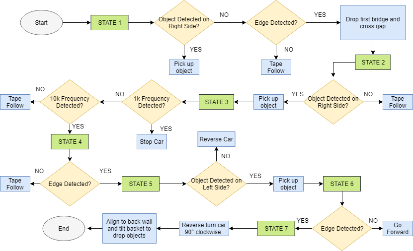
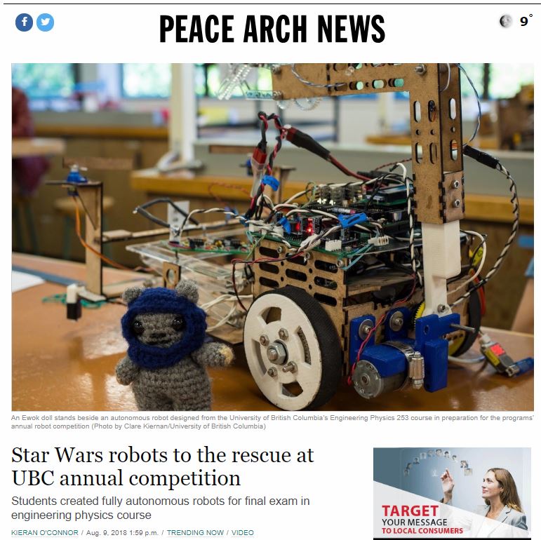
LYSANDEROTH
  • Priyansh Malik
  • Devika Vishwanath
  • Samia Siddique Sama
  • Shafkat Khondker

GOAL

Build an autonomous robot that can line follow, detect edges, avoid obstacles, cross gaps, detect and distinguish between infrared frequencies, detect and pick up Ewoks and return them to the safety start position.

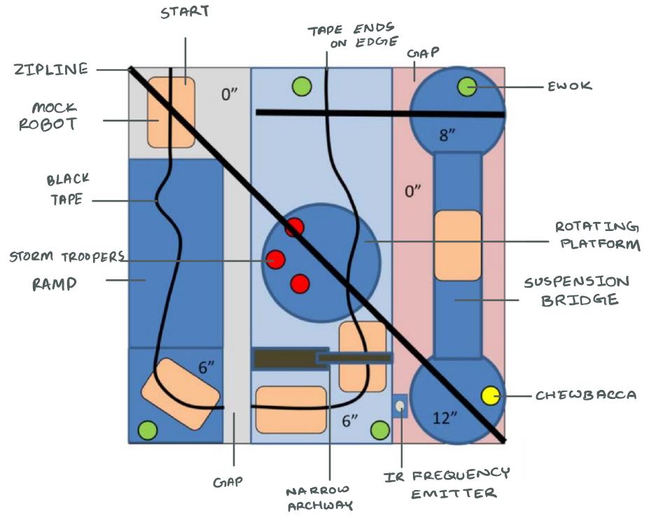
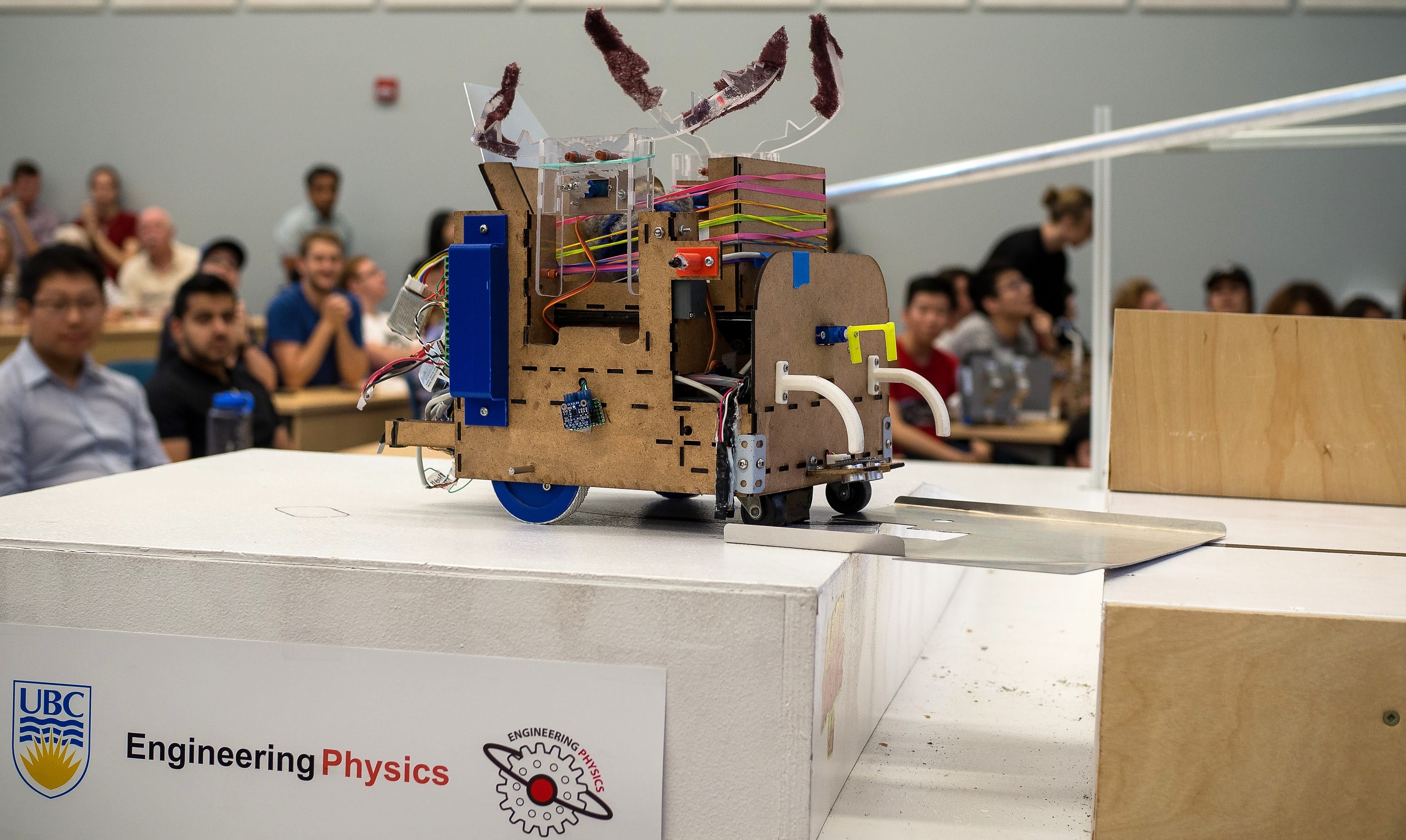
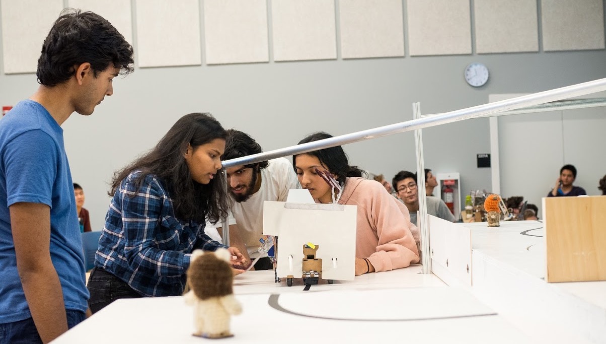
A mock-up of the competition surface highlighting some of the biggest obstacles to overcome.

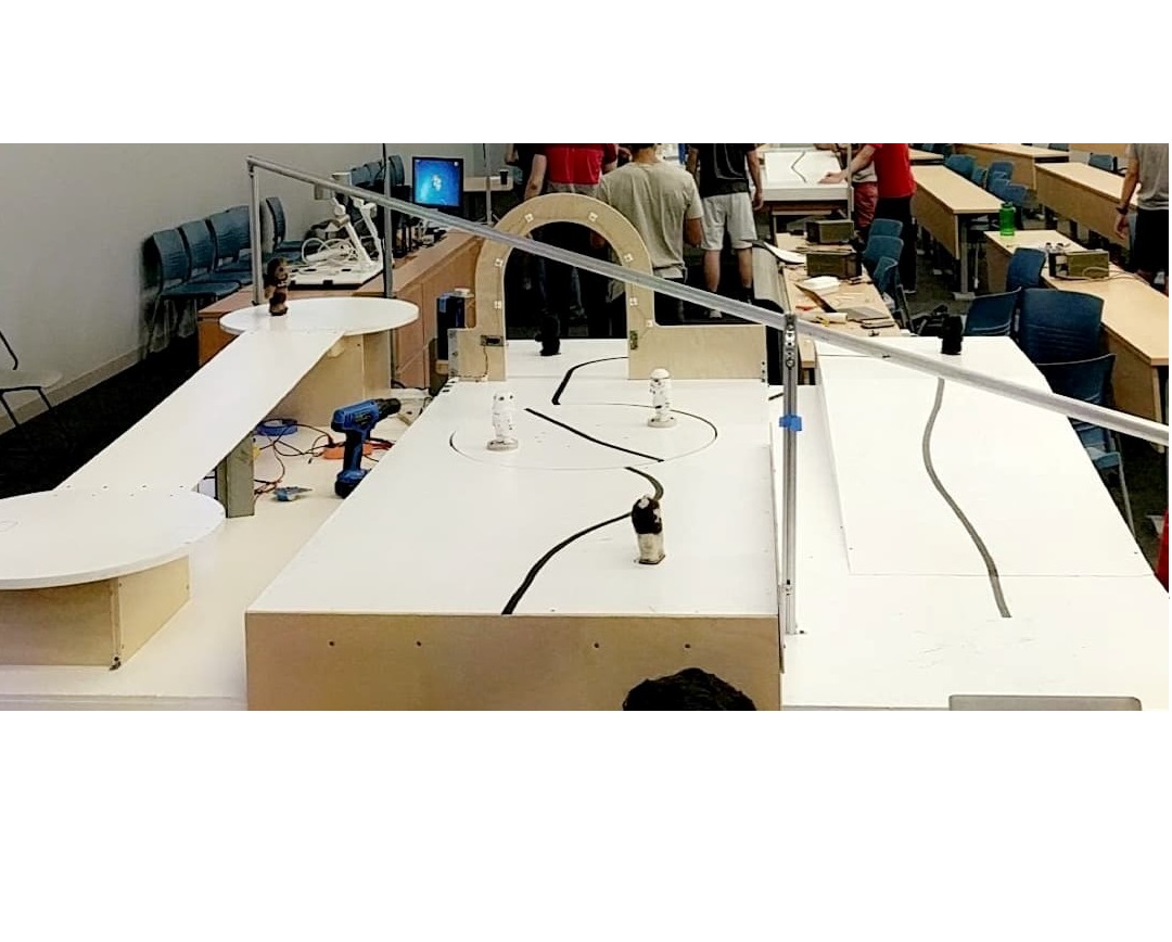
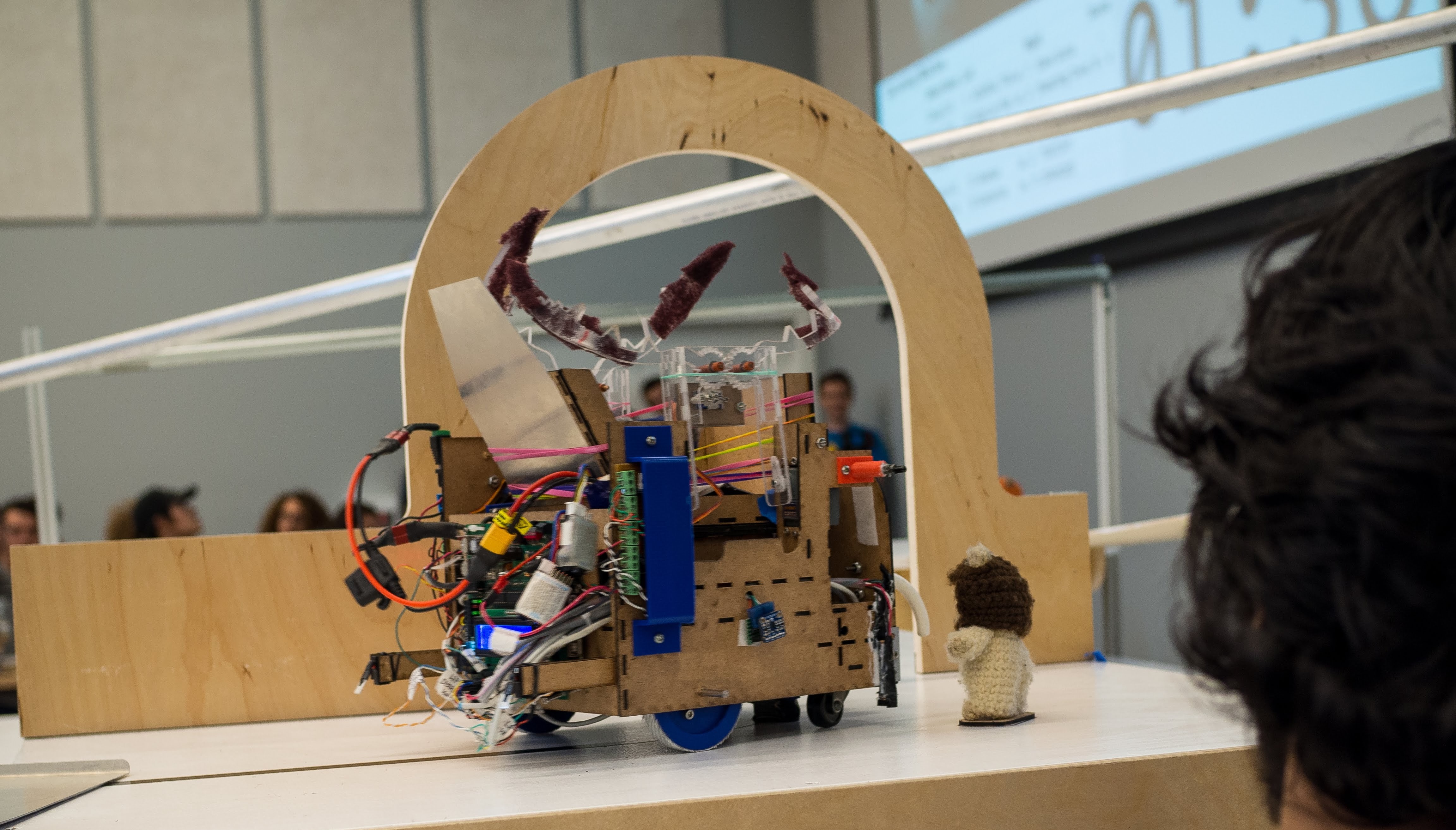
The competition surface where teams went head to head to pick up and return the maximum number of Ewoks within 2 minutes.

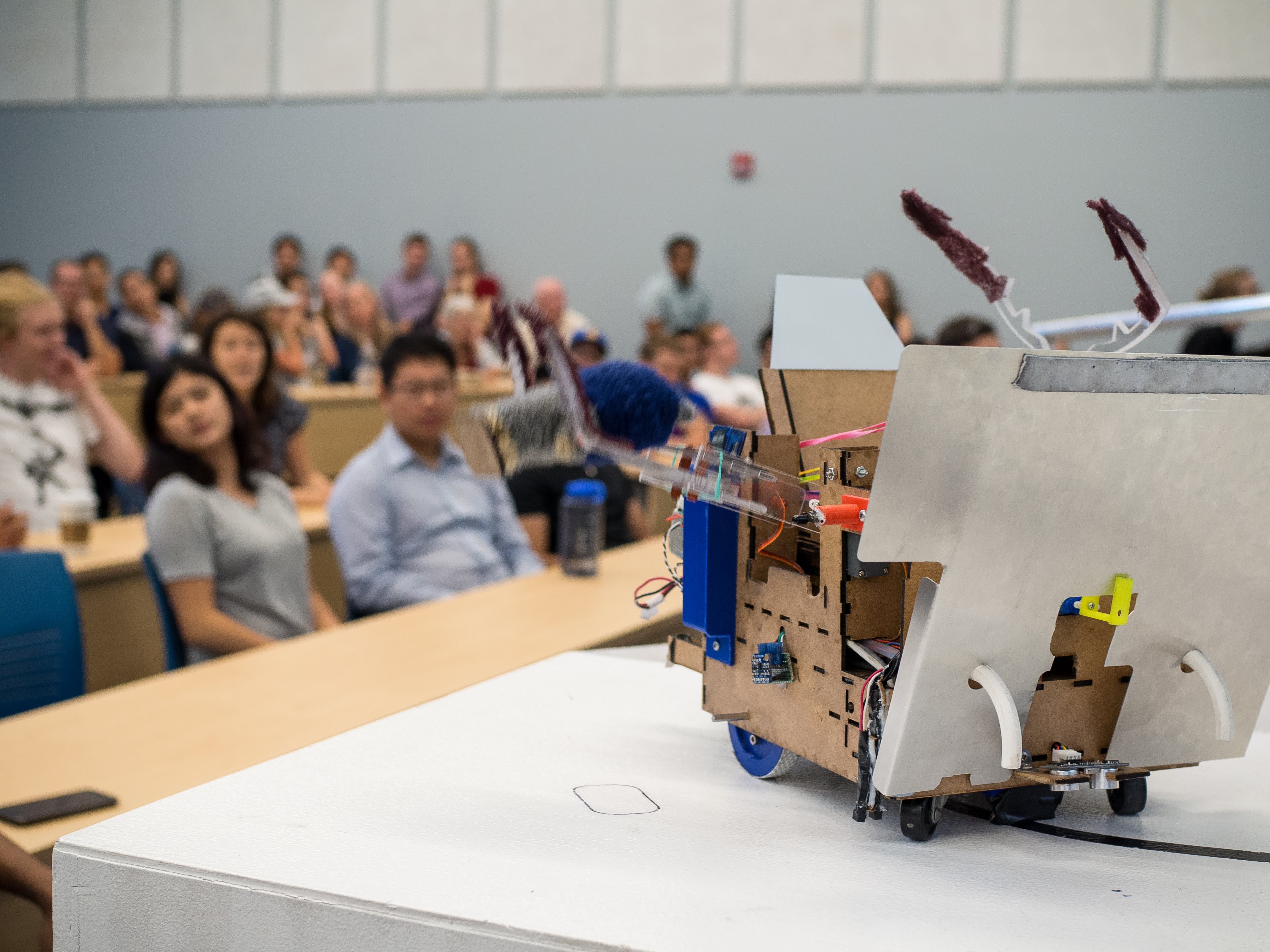
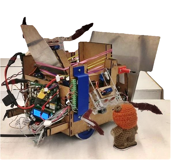
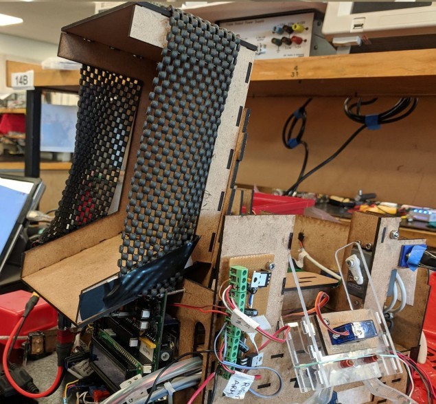
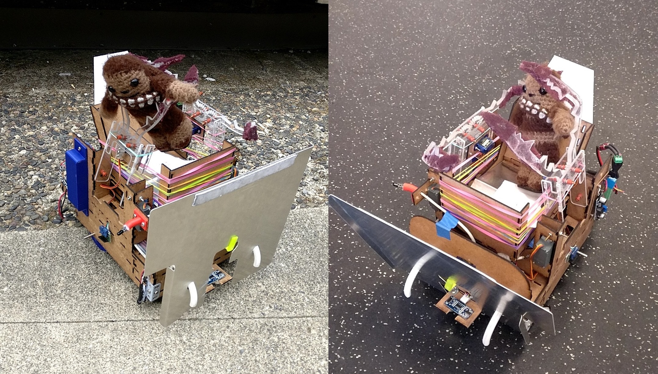
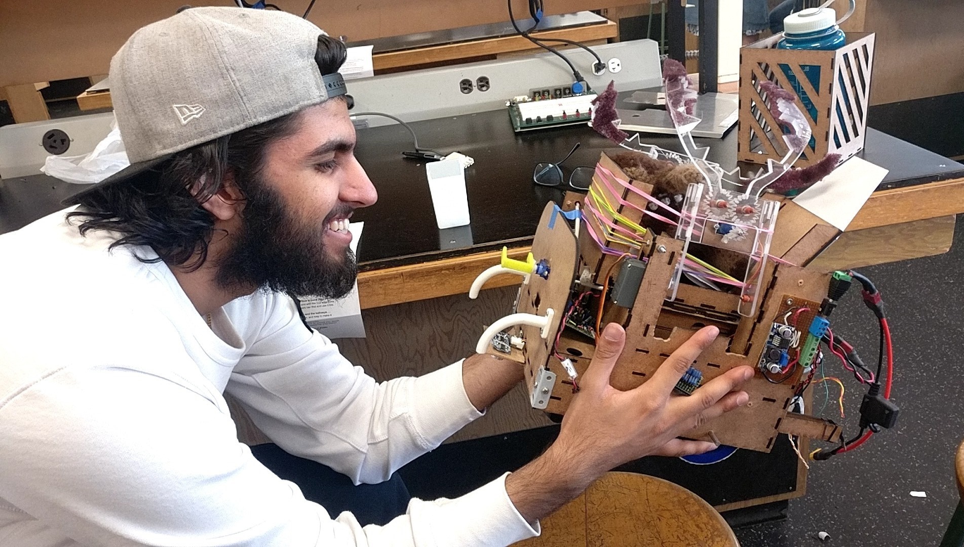
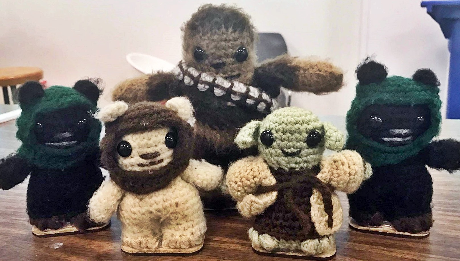
Lysanderoth picking up an Ewok

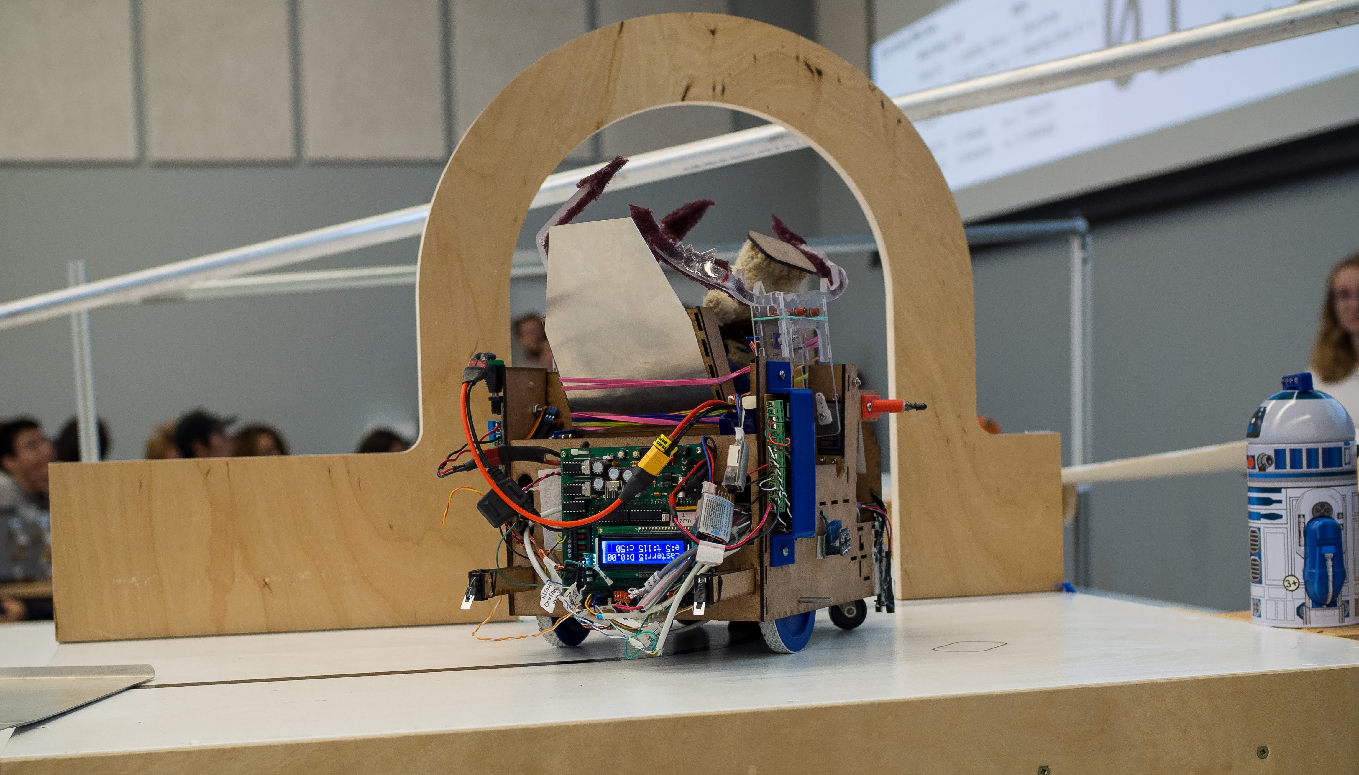
Lysanderoth in action; successfully picking up and returning 3 Ewoks under a minute.

MECHANICAL

CAD Model of Chassis

Chassis

  • After designing a CAD model of our chassis using Solidworks and Onshape we laser cut individual parts and assembled using tab and slot joint method.
  • Our final chassis had
    • Space on the rear and underside for electrical components
    • Claws mounted on the sides of the chassis
    • A scissor lift/zipline mechanism mounted on the base

Drive Train

  • The drive train was designed to allow for a compact chassis and simple chassis
  • The robot is powered using two geared Barber-Coleman motors with a gear ratio of 3:1
  • Motor mounts were designed using Onshape and 3D printed. This dampened the vibrations and provided a secure hold on the motors.

Claws

  • A claw was mounted on both sides of the robot which allowed for decreased uncertainty in retrieving objects.
  • The small size of the claws allows for the robot to fit between the arch way with ease
  • The claw system was designed to cover as wide range of area as possible allowing for consistent results regardless of object placement.
  • The claws arms were curved to maximize contact area with objects
  • A polycarbonate build allowed the claw mechanism to be extremely robust

Bridge System

  • To cross the gaps the robot used two sheet metal bridges
  • A single servo was used to drop the bridge when an edge is detected
  • The cut outs in the bridges helped ensure one servo can drop both bridges at different times
  • The sides of the bridges were curved to brush against the robot if the robot was a bit disaligned

Basket Lift

  • To return the collected Ewoks back to friendly territory a basket lifting mechanism was utilized in conjunction with the competition surface zipline
  • A scissor lift mounted onto the base of the robot was used to lift the basket and hook onto a metal zipline
  • A Barber-Coleman motor was used with a lead screw to increase and decrease height of the platform

Tilt Lift

  • To return the first 3 Ewoks back to start the robot included a basket tilting mechanism
  • A servo motor tilts the basket filled with Ewoks when limit switches on the rear of the car are pressed.
  • Allows for certainty in position when carrying out the dropping action

Electrical

Infrared Frequency Detection

The circuit was used to detect 10kHz and 1kHz frequency, which was processed in the microcontroller

Soldered IR Circuit

  • The IR circuit detects and distinguishes between 10kHz signal and 1kHz signal emitted from an IR beacon.
  • The outputs from the circuit is fed into the Analog inputs of the microcontroller.
  • The OpAmps are easily replaceable since we soldered 8 pin sockets onto the PCB.
  • Due to the modular design of the PCB, it was very easy to debug the IR circuit.
  • Using a potentiometer helped us to adjust the gain of the amplifier according to different IR beacons.
  • The IR circuit was one of the most reliable components of our robot.

H-Bridge

H-bridges were used to control the motor direction of the robot.

Two Soldered H-bridge circuits secured under the chassis

  • Although the microcontoller has built in H-bridges, it can supply only limited current; therefore, we used external H-bridges.
  • We supplied a regulated voltage of 15V to the motors from a LiPo battery.
  • The MOSFETs we used for the H-bridge were fully replaceable since we used female header pins on the PCB. This saved us a lot of time since we did not have to remake PCBs.
  • The well-thought-out compact design helped us to fit the H-bridges under the chassis.
  • The H-bridges were secured onto a separate PCB bolted under the Chassiss using male and female header pins. This made the circuits easily removable and easy to debug

Sensors

Distance Sensor for Object Detection

Two VL53L0X Time-of-Flight distance sensors were used on either side to accurately detect the Ewoks. Using a state machine we controlled turning on and off the sensors to avoid false detection.

QRD for Line Following

Two QRD's placed the width of black tape apart to detect voltage difference due to contrast. The QRD's were very close to the ground, enclosed in a casing to reduce noisy signal. PID control was used to line follow.

Phototransistor for IR detection

The phototransistor was securely held in a casing at an angle based on the position of the robot on the track relative to the frequency generator, to ensure maximum exposure to IR.

Sonar for Edge Sensing

Sonar's placed ahead of the robot ensured edge detection ahead of time and allowed to check for false edges by taking multiple readings and taking the average.

Software

Micro-controller

TINAH Micro-controller

TINAH is an extension shield designed and built for the ENPH 253 course. The TINAH board connects to the Wiring Board, an open-source electronics IO board that is similar to Arduino boards.The TINAH board design was inspired by the Handyboard, a Motorola 6811-based microcontroller system designed for educational, hobbyist, and industrial robotics applications. Available features:

  • Four DC motor outputs connected to on-board H-bridge drivers (9V, 1A/motor)
  • Three RC Servo motor outputs
  • Buffered digital and analog IO pins (for protecting the Wiring board)
  • Two buttons and two knobs for on-board control
  • T16×2 character LCD
  • Enable and direction pins for external motor control (5V logic)

Simplified State Machine

We used an event based state machine for the decision making process of our robot. The diagram above highlights the logic used during each state and the events that triggered a change in state.

Complete State Diagram

C++ Code

Improvements

Technical

  • Spending more time on the overall wiring design at the beginning.
  • Solder the tips of all header pins going into the TINAH in order to ensure secure connections.
  • Take into consideration the weight distribution of the chassis in order to prevent it from tilting back while going up the second bridge.
  • Easily replaceable mechanical components, such as the servo motors.
  • A second IR circuit soldered as a backup, as that was the most time consuming circuit to make.
  • Start writing the software from the very begining instead of waiting for a physical prototype.

Logistics

  • Accounting for the time for debugging while planning project timelines.
  • Better time management in terms of not staying stuck on one component for a long time; instead moving on to something else and asking for help when available.
  • Put more effort into following gantt chart, and making a revised gantt chart.

Media Coverage

News Covered By: BC CTV

News Covered By: Peace Arch News

Photo Gallery